


|
Solid Geometry TutorialTeapot Construction 101ContentsIntroductionCommons Geometry contains a number of methods for manipulating solid, 3D dimensional figures. These geometric figures can be combined in various ways to produce new figures. In this tutorial, we will explore these features by constructing a 3D model of a teapot from scratch. The image below shows the result of our efforts. The final code for this tutorial can be found in the TeapotBuilder class, which is included in the library source distribution. NOTE: All images used in this tutorial have been rendered using Blender. 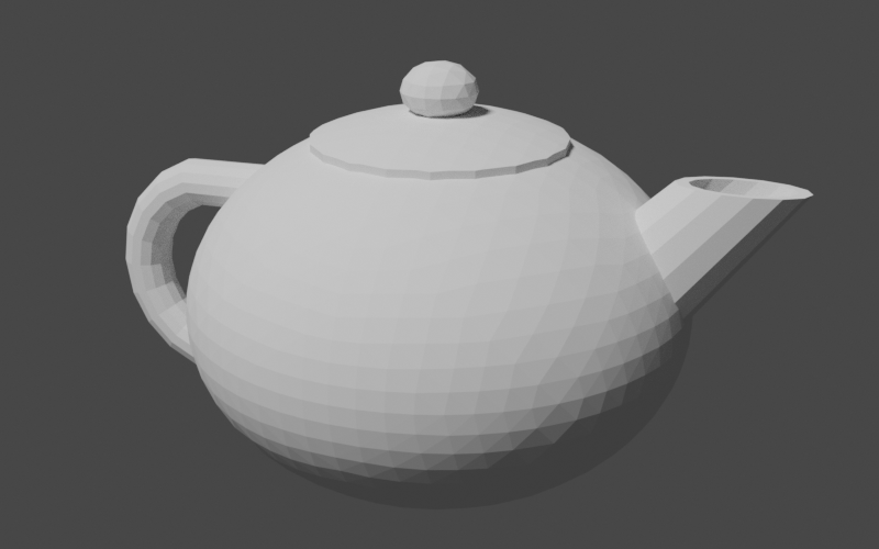
Getting StartedThe first step we will take on our journey is the creation of a class encapsulating our teapot construction logic, aptly named TeapotBuilder. The constructor will accept only a single argument: an instance of Precision.DoubleEquivalence from the Commons Numbers library. This is a ubiquitous type in Commons Geometry and is used to provide a method of comparing floating point numbers without being susceptible to small floating point errors introduced during computations. Typically, users of Commons Geometry will construct a single instance of this type for use by multiple objects throughout an entire operation, or even application. Since we don't want our class to assume such a heavy responsibility, we will simply accept an instance in the constructor.
public class TeapotBuilder {

    private final Precision.DoubleEquivalence precision;

    public TeapotBuilder(final Precision.DoubleEquivalence precision) {
        this.precision = precision;
    }
}
Next, we will create a stub method for our teapot-building code. We will fill in this method as we work through the tutorial.
public RegionBSPTree3D buildTeapot() {
    // TODO: actually build a teapot here

    return RegionBSPTree3D.empty();
}
We have chosen the RegionBSPTree3D type for both the construction of the teapot geometry as well as the return value. This is the primary type in Commons Geometry for manipulating solid geometries. (There are similar such types for each space and dimension supported by the library, such as RegionBSPTree2D for 2D Euclidean space and RegionBSPTree2S for 2D spherical space.) This type uses a binary space partitioning (BSP) tree to represent arbitrary regions of space, including regions of infinite size. This is accomplished by recursively dividing a space in two by partitioning planes (or "hyperplanes", to use the more general term). The spaces on either side of the planes are then given the labels "inside" or "outside". A region is composed of all of the "inside" portions of the BSP tree. A major benefit of using BSP trees to represent regions is that it allows us to perform boolean operations such as union, intersection, difference, and xor on arbitrary regions. We will use these operations to combine simple shapes to construct our teapot. Before constructing our first geometry, we need to handle one more bit of housekeeping, namely, how to view our work. The easiest way to do this is to export our geometries using a common 3D file format, such as STL, and view the model in a 3D modeling program. I enjoy working with Blender so that is the modeling program I have chosen to use for this tutorial. However any program able to load and display 3D models should work. To create our geometry files, we will use the 3D file writing capabilities of Commons Geometry accessible through the IO3D convenience class. See the GeometryFormat3D enum for a list of supported file formats.
TeapotBuilder builder = new TeapotBuilder(precision);

RegionBSPTree3D teapot = builder.buildTeapot();

IO3D.write(teapot, Paths.get("teapot.stl"));
With this bit of code place, we are ready to start creating geometry! Building the PartsOur teapot will contain four main parts: the body, the lid, the handle, and the spout. We will create private methods for each of theses parts in our TeapotBuilder class. Later, we will combine the outputs of these methods to form the final geometry. The BodyThe first part we will construct is the teapot body. We will start by creating a private method named buildBody in our builder class and referencing it in our main build method. We'll return the body directly for the time being so we can view the output.
public RegionBSPTree3D buildTeapot() {
    // build parts
    RegionBSPTree3D body = buildBody();

    // TODO: combine into the final region

    return body; // return for debugging
}

private RegionBSPTree3D buildBody() {
    // TODO
    return RegionBSPTree3D.empty();
}
Unlike some fancier types you might see, our teapot is going to have a simple, rounded body. So, we will start by creating a sphere and go from there. Luckily, Commons Geometry provides a Sphere class to help us. Sphere sphere = Sphere.from(Vector3D.ZERO, 1, precision); We now have a Sphere instance centered on the origin with a radius of 1. However, our instance represents an analytic sphere, meaning it is does not contain any flat surfaces. This is great for many use cases, but we need flat surfaces in order to construct a BSP tree. To convert from our mathematically perfect sphere abstraction to a BSP tree sphere approximation, we will use the Sphere.toTree() method. This method accepts a single argument that determines the number of facets that will be used in the approximation. The documentation explains the details of the conversion. For our purposes, we will use the argument 4, which will give us a BSP tree with 2048 facets. Sphere sphere = Sphere.from(Vector3D.ZERO, 1, precision); RegionBSPTree3D body = sphere.toTree(4); This finally gives us something we can look at in our 3D modeling program. 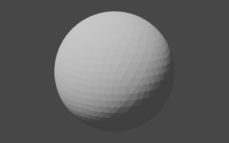
Our next step is to tweak the sphere to make it more teapot-like. First, we will squash it vertically a little to make it less of a perfect sphere. Our tool of choice for this squashing exercise is the AffineTransformMatrix3D class, which we will be using quite frequently in the remainder of this tutorial. This class represents a 4x4 transform matrix that can be used to perform affine transformations in 3D space. In short, it lets us perform operations like translate, scale, and rotate on geometries. Here, we will use it to scale down our sphere approximation along the z-axis, while keeping the x and y axes the same. AffineTransformMatrix3D t = AffineTransformMatrix3D.createScale(1, 1, 0.75); body.transform(t); Our sphere now looks flattened a bit. 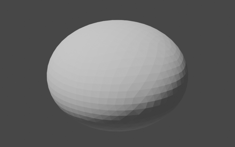
Note that our choice to scale along the z-axis (as opposed to the x or y axes) was completely arbitrary; our sphere was entirely symmetrical and we had no definition of what was "up" and what was "down" as it relates to our teapot. Now that we have performed our first non-symmetrical operation, we should officially declare the orientation of our teapot: henceforth the positive z-axis will be "up" and the the positive x-axis will be "forward" (the direction that the spout is pointing) in "teapot-space". Keeping this orientation in mind will help us when working through later transformations. Our teapot is now pleasantly flattened but it is still very likely to roll off tables and create all manner of messes. To address this shortcoming, we will chop off part of the bottom to make a flat base for the teapot to sit on. In code, we will define this plane, construct a region of infinite size with that plane as the "top", and compute the difference between our flattened sphere and the infinite region.
Plane bottomPlane = Planes.fromPointAndNormal(
        Vector3D.of(0, 0, -0.6),
        Vector3D.Unit.PLUS_Z,
        precision);
PlaneConvexSubset bottom = bottomPlane.span();
body.difference(RegionBSPTree3D.from(Arrays.asList(bottom)));
There's a lot going on in just a few lines here so let's go through it step by step.
Plane bottomPlane = Planes.fromPointAndNormal(
        Vector3D.of(0, 0, -0.6),
        Vector3D.Unit.PLUS_Z,
        precision);
Here we construct a plane from an arbitrary point lying in the plane, the plane normal, and our good friend Precision.DoubleEquivalence. We choose a point that is directly "below" the origin (per our previous definition of teapot-space) and that will cause the plane to intersect the bottom of the teapot body. The plane normal points "up", along the positive z axis. PlaneConvexSubset bottom = bottomPlane.span(); This may well be the most confusing line in this section. This line constructs a PlaneConvexSubset that represents all of the points in the plane we just created. These seem like equivalent concepts — a plane and another object that represents the exact same set of points — but they're slightly different. The plane defines what points are available, while the convex subset selects (in an abstract sense) a convex group of those points. Examples of plane convex subsets include triangles, convex polygons, plane half-spaces, and, as in this case, every single last point in the entire plane (i.e., the "span"). These concepts are generalized to all geometric spaces and dimensions with the Hyperplane and HyperplaneConvexSubset interfaces. The reason we needed to convert from a Plane to a PlaneConvexSubset in the first place is that BSP trees are constructed from plane convex subsets and not planes. This brings us to the next line. body.difference(RegionBSPTree3D.from(Arrays.asList(bottom))); This line constructs a BSP tree from our bottom plane convex subset and then computes the difference between body and the new BSP tree, storing the result back into body. When BSP trees are constructed from plane convex subsets, the inside of the region is by default the part opposite the direction of the plane normal. Since we constructed our plane with the normal along the positive z-axis (i.e. "up"), the inside of our BSP tree is everything from our plane "down" along the negative z-axis. When we subtract this from the body, we end up with a rounded top and a flat bottom. 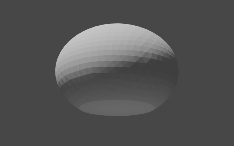
The LidNext, we will make the lid of our teapot. As before, we will begin by creating a helper method and referencing it in the main build method.
public RegionBSPTree3D buildTeapot() {
    // build parts
    RegionBSPTree3D body = buildBody();
    RegionBSPTree3D lid = buildLid(body);

    // TODO: combine into the final region

    return lid; // return for debugging
}

private RegionBSPTree3D buildLid(RegionBSPTree3D body) {
    // TODO
    return RegionBSPTree3D.empty();
}
You may be wondering why we passed the body BSP tree to our new method. The reason is that we want the top of the lid to match the curve of the body exactly and the best way to do that is to have access to the body itself. Our overall plan of attack here will be to
RegionBSPTree3D lid = body.copy();

AffineTransformMatrix3D t = AffineTransformMatrix3D.createTranslation(0, 0, 0.03);
lid.transform(t);
Our lid is now slightly raised above the body and matches its curve exactly. Unfortunately, the lid is also the same size as the body which makes its job as lid somewhat difficult. We need to trim it to have a radius less than the radius of the body, but how do we do that? One option is to intersect it with a cylinder of the appropriate radius. If the cylinder is oriented along the positive z-axis ("up"), then it will trim off the parts of the body that we don't want while retaining the curved top. Perfect. Now all we need is a way to construct a cylinder with the correct dimensions. It sounds like we need another helper method. There are many ways we could go about creating our cylinder helper method. We could, for example, have it return a BSP tree like all of our other methods so far. This would work in the case of the lid. However, for other parts of the teapot, we are going to want fine-grain control over the position of the cylinder vertices. Therefore, we will design our helper method to return a TriangleMesh, which will give us the precise vertex placement that we need. The method will accept 3 arguments:
private TriangleMesh buildUnitCylinderMesh(int segments, int circleVertexCount,
        UnaryOperator<Vector3D> vertexTransform) {
    // TODO
    return null;
}
We will use the SimpleTriangleMesh class to build our mesh. This class has a builder type that allows us to easily define vertices and faces. SimpleTriangleMesh.Builder builder = SimpleTriangleMesh.builder(precision); Next, we will define the vertices. As mentioned above, the cylinder will initially be constructed along the positive z-axis with z values in the range 0 to 1. The cylinder vertices will then be transformed to their final locations using the function supplied by the caller. The final vertex locations do not affect the face definitions, however, so after this step we can continue on with the rest of cylinder construction as if the vertices were in their original locations.
double zDelta = 1.0 / segments;
double zValue;

double azDelta = Angle.TWO_PI / circleVertexCount;
double az;

Vector3D vertex;
for (int i = 0; i <= segments; ++i) {
    zValue = (i * zDelta);

    for (int v = 0; v < circleVertexCount; ++v) {
        az = v * azDelta;

        vertex = Vector3D.of(
                Math.cos(az),
                Math.sin(az),
                zValue);
        builder.addVertex(vertexTransform.apply(vertex));
    }
}
Now come the face definitions. We need to define the faces on the bottom, sides, and top of the cylinder, making sure at each step that the triangle normals point outward.
// add the bottom faces using a triangle fan, making sure
// that the triangles are oriented so that the face normal
// points down
for (int i = 1; i < circleVertexCount - 1; ++i) {
    builder.addFace(0, i + 1, i);
}

// add the side faces
int circleStart;
int v1;
int v2;
int v3;
int v4;
for (int s = 0; s < segments; ++s) {
    circleStart = s * circleVertexCount;

    for (int i = 0; i < circleVertexCount; ++i) {
        v1 = i + circleStart;
        v2 = ((i + 1) % circleVertexCount) + circleStart;
        v3 = v2 + circleVertexCount;
        v4 = v1 + circleVertexCount;

        builder
            .addFace(v1, v2, v3)
            .addFace(v1, v3, v4);
    }
}

// add the top faces using a triangle fan
int lastCircleStart = circleVertexCount * segments;
for (int i = 1 + lastCircleStart; i < builder.getVertexCount() - 1; ++i) {
    builder.addFace(lastCircleStart, i, i + 1);
}

return builder.build();
That should do it! Now we can use this in our lid construction, making sure to pass a transform that will give us the radius that we want with enough height to make sure we don't miss any part of the top. We'll use the toTree() method of the mesh to directly convert the mesh geometry into a BSP tree. TriangleMesh cylinder = buildUnitCylinderMesh(1, 20, AffineTransformMatrix3D.createScale(0.5, 0.5, 10)); lid.intersection(cylinder.toTree()); 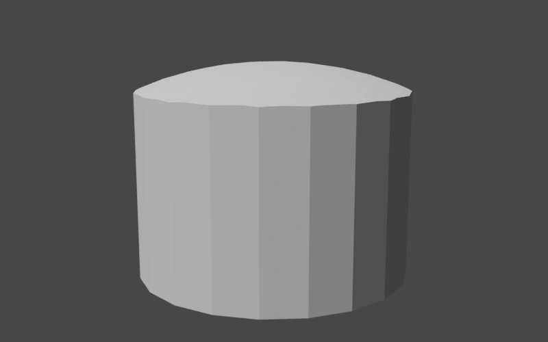
The fact that the lid is extremely thick does not matter for our purposes. We will be merging it with the teapot body soon and the lower portion will simply become part of the body. All that's left now is the small rounded handle on top of the lid. We've already done something similar for the body so this should be simple. The only difference from before is that we will be using the axis-aligned bounding box of the lid to help place the handle in the correct location.
Sphere sphere = Sphere.from(Vector3D.of(0, 0, 0), 0.15, precision);
RegionBSPTree3D sphereTree = sphere.toTree(2);

Bounds3D lidBounds = lid.getBounds();
double sphereZ = lidBounds.getMax().getZ() + 0.075;
sphereTree.transform(AffineTransformMatrix3D.createScale(1, 1, 0.75)
        .translate(0, 0, sphereZ));

lid.union(sphereTree);
This completes our teapot lid. 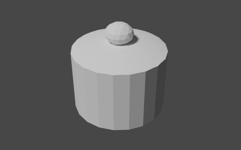
The HandleConstructing the handle of our teapot is going to be something of an adventure; not only will we need to apply scaling and translations to our starting geometry, we will need to interpolate between a range of 3D rotations. In this case, perhaps it would be best to see the end product first before we jump into the details. That will give us a frame of reference for what we're working toward. Below is our goal for the handle. 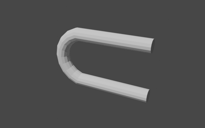
As you can see, the handle is a long, straight cylinder that we've curved back on itself, leaving straight sections at the beginning and end. This means that we can use our new cylinder mesh helper method to construct the shape. Let's start by adding the private builder method to our class, leaving a placeholder for the portion where we manipulate the position of the cylinder.
public RegionBSPTree3D buildTeapot() {
    // build parts
    RegionBSPTree3D body = buildBody();
    RegionBSPTree3D lid = buildLid(body);
    RegionBSPTree3D handle = buildHandle();

    // TODO: combine into the final region

    return handle; // return for debugging
}

private RegionBSPTree3D buildHandle() {
    UnaryOperator<Vector3D> vertexTransform = v -> {
        // TODO
        return v;
    };

    return buildUnitCylinderMesh(10, 14, vertexTransform).toTree();
}
We now have the start of our handle in place. Note that we've used a larger number of cylinder segments (14) so we have enough to smoothly curve the shape. Since we're not modifying the shape of the cylinder yet, our handle looks like this. 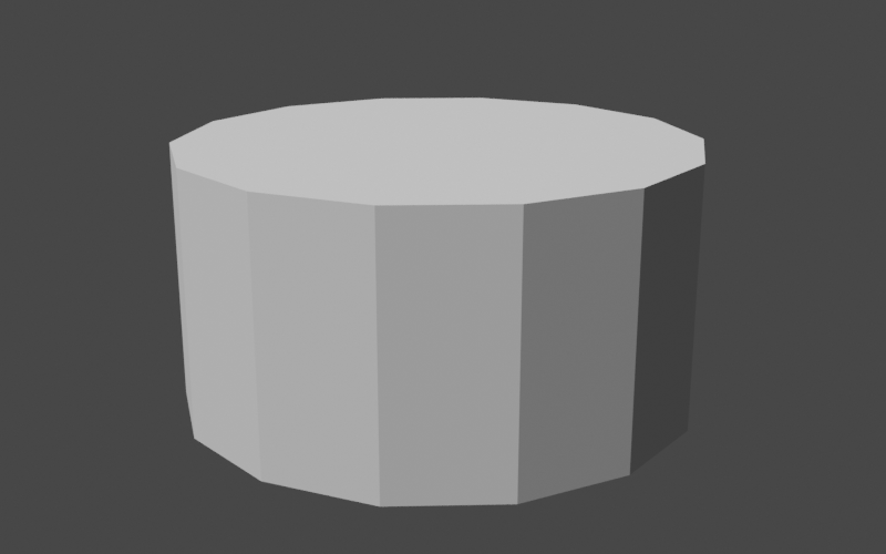
The handle is a cylinder with a radius of 1 and a height (along the positive z-axis) of 1 with its base at the origin. We will need to apply scaling, rotation, and translation to get this cylinder into the correct shape and location. The scaling is no problem since we've already done that several times. We want our handle to have a radius of 0.1 so we scale by that factor in the x and y axes. For the z-axis (height), we'll leave the value at 1 for now.
double handleRadius = 0.1;
double height = 1;

AffineTransformMatrix3D scale = AffineTransformMatrix3D.createScale(handleRadius, handleRadius, height);

UnaryOperator<Vector3D> vertexTransform = v -> {
    return scale.apply(v);
};

return buildUnitCylinderMesh(10, 14, vertexTransform).toTree();
This gives our handle the thickness that we want. 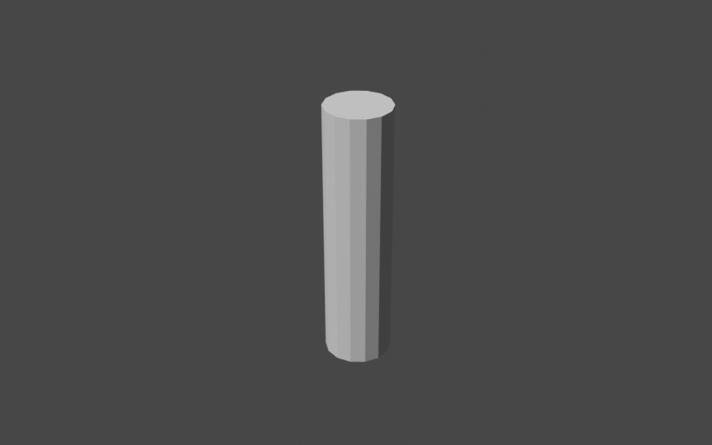
Now on to the tricky bit: the rotation. The QuaternionRotation class is the go-to class in Commons Geometry for rotations in 3D. Instances of this class can be pictured as representing a rotation of a certain angle around some axis in 3D space. If we applied the same rotation to all vertices in our cylinder, the entire thing would rotate but retain the same shape. This is not what we want. We want a curve in the middle of the handle, which means we need to apply different rotations to different vertices. Our tool for this is the Slerp (spherical linear interpolation) algorithm. This algorithm smoothly interpolates between a start and stop quaternion rotation, giving us the series of rotations that we need for our curve. Let's create our slerp function in code. QuaternionRotation startRotation = QuaternionRotation.fromAxisAngle(Vector3D.Unit.PLUS_Y, -Angle.PI_OVER_TWO); QuaternionRotation endRotation = QuaternionRotation.fromAxisAngle(Vector3D.Unit.PLUS_Y, Angle.PI_OVER_TWO); DoubleFunction<QuaternionRotation> slerp = startRotation.slerp(endRotation);
We've defined our rotation sequence as starting at -π/2 around the y-axis and ending at
+π/2 around the y-axis. This gives the full rotation an angle of π, or 180 degrees.
The expression Let's apply our new slerp function to the cylinder. Since the cylinder z-values range from 0 to 1, they make the perfect argument to pass to slerp to determine the rotation for each vertex. When we apply the rotation, we need to keep the following in mind:
double t = v.getZ(); Vector3D scaled = scale.apply(v); QuaternionRotation rot = slerp.apply(t); AffineTransformMatrix3D mat = AffineTransformMatrix3D.createRotation(curveCenter, rot); return mat.apply(Vector3D.of(scaled.getX(), scaled.getY(), 0)); 
Looks good! We only need a few more tweaks:
double handleRadius = 0.1;
double height = 1 - (2 * handleRadius);
AffineTransformMatrix3D scale = AffineTransformMatrix3D.createScale(handleRadius, handleRadius, height);
QuaternionRotation startRotation = QuaternionRotation.fromAxisAngle(Vector3D.Unit.PLUS_Y, -Angle.PI_OVER_TWO);
QuaternionRotation endRotation = QuaternionRotation.fromAxisAngle(Vector3D.Unit.PLUS_Y, Angle.PI_OVER_TWO);
DoubleFunction<QuaternionRotation> slerp = startRotation.slerp(endRotation);
Vector3D curveCenter = Vector3D.of(0.5 * height, 0, 0);
AffineTransformMatrix3D translation = AffineTransformMatrix3D.createTranslation(Vector3D.of(-1.38, 0, 0));
UnaryOperator<Vector3D> vertexTransform = v -> {
double t = v.getZ();
Vector3D scaled = scale.apply(v);
QuaternionRotation rot = slerp.apply(t);
AffineTransformMatrix3D mat = AffineTransformMatrix3D.createRotation(curveCenter, rot);
Vector3D rotated = mat.apply(Vector3D.of(scaled.getX(), scaled.getY(), 0));
Vector3D result = (t > 0 && t < 1) ?
rotated :
rotated.add(Vector3D.Unit.PLUS_X);
return translation.apply(result);
};
return buildUnitCylinderMesh(10, 14, vertexTransform).toTree();Voilà.
The SpoutNow that we have the handle under our belt, the spout will be a piece of cake. Our general approach will be the same as the handle, where we begin with a cylinder and transform the mesh vertices into their final positions. Instead of a curve, however, we will be creating a taper and a shear. Let's create our method stub to start.
public RegionBSPTree3D buildTeapot() {
    // build parts
    RegionBSPTree3D body = buildBody();
    RegionBSPTree3D lid = buildLid(body);
    RegionBSPTree3D handle = buildHandle();
    RegionBSPTree3D spout = buildSpout();

    // TODO: combine into the final region

    return spout; // return for debugging
}

private RegionBSPTree3D buildSpout() {
    UnaryOperator<Vector3D> vertexTransform = v -> {
        // TODO
        return v;
    };

    return buildUnitCylinderMesh(10, 14, vertexTransform).toTree();
}
We'll start with the taper. We want the spout to be an oval that is wider at the base and narrower near the top. We can represent this as a two different scalings in the horizontal plane and store the scale factors in 2D vectors. We'll define the factors for the base and then simply compute the factors for the top as a multiple of that. The scaling for each vertex is then a linear interpolation between the two, with the vertex z value as the interpolation parameter. We'll use the vector lerp method to perform the interpolation.
Vector2D baseScale = Vector2D.of(0.4, 0.2);
Vector2D topScale = baseScale.multiply(0.6);

UnaryOperator<Vector3D> vertexTransform = v -> {
    Vector2D scale = baseScale.lerp(topScale, v.getZ());

    Vector3D tv = Vector3D.of(
                v.getX() * scale.getX(),
                v.getY() * scale.getY(),
                v.getZ()
            );

    return tv;
};

return buildUnitCylinderMesh(1, 14, vertexTransform).toTree();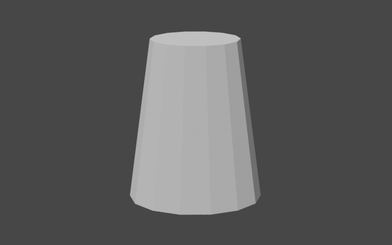
Now for the shear, or slant, in the positive x direction. This is simply a multiple of the vertex z value that we add to the x value. While we're at it, we'll also translate the spout to its final position in the teapot.
Vector2D baseScale = Vector2D.of(0.4, 0.2);
Vector2D topScale = baseScale.multiply(0.6);
double shearZ = 0.9;

AffineTransformMatrix3D translation = AffineTransformMatrix3D.createTranslation(Vector3D.of(0.25, 0, -0.4));

UnaryOperator<Vector3D> vertexTransform = v -< {
    Vector2D scale = baseScale.lerp(topScale, v.getZ());

    Vector3D tv = Vector3D.of(
                (v.getX() * scale.getX()) + (v.getZ() * shearZ),
                v.getY() * scale.getY(),
                v.getZ()
            );

    return translation.apply(tv);
};

return buildUnitCylinderMesh(1, 14, vertexTransform).toTree();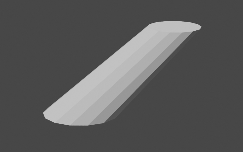
Putting it all togetherNow that we have all of the parts of our teapot in place we can begin combining them to construct the full teapot. We simply need to compute the union of all of the parts using the BSP tree union method.
public RegionBSPTree3D buildTeapot(Map<String, RegionBSPTree3D> debugOutputs) {
    // build the parts
    RegionBSPTree3D body = buildBody(1);
    RegionBSPTree3D lid = buildLid(body);
    RegionBSPTree3D handle = buildHandle();
    RegionBSPTree3D spout = buildSpout(1);

    // combine into the final region
    RegionBSPTree3D teapot = RegionBSPTree3D.empty();
    teapot.union(body, lid);
    teapot.union(handle);
    teapot.union(spout);

    return teapot;
}
Note that we've used two different forms of the union method: a two argument version and a one
argument version. In both cases, the result is stored in the caller and the arguments are unchanged. The
two argument version is designed for use when the caller is not involved in the computation and can be
completely overwritten. For example, the call Now that all of the parts are combined, we can finally view our teapot. 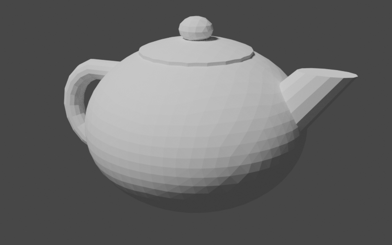
It looks pretty good! One thing is off, though: our teapot is completely solid. In order to make it hollow like a real teapot, we'd need to hollow out the body and the interior of the spout. Luckily, we can do this with just a few small tweaks to our code: we can add parameters to our body and spout construction methods that control the overall size of the produced region. We can then subtract these smaller regions from the teapot to hollow it out.
public RegionBSPTree3D buildTeapot() {
    // build the parts
    RegionBSPTree3D body = buildBody(1);
    RegionBSPTree3D lid = buildLid(body);
    RegionBSPTree3D handle = buildHandle();
    RegionBSPTree3D spout = buildSpout(1);

    // combine into the final region
    RegionBSPTree3D teapot = RegionBSPTree3D.empty();
    teapot.union(body, lid);
    teapot.union(handle);
    teapot.union(spout);

    // subtract scaled-down versions of the body and spout to
    // create the hollow interior
    teapot.difference(buildBody(0.9));
    teapot.difference(buildSpout(0.8));

    return teapot;
}

private RegionBSPTree3D buildBody(double initialRadius) {
    Sphere sphere = Sphere.from(Vector3D.ZERO, initialRadius, precision);

    // ...

    Plane bottomPlane = Planes.fromPointAndNormal(
            Vector3D.of(0, 0, -0.6 * initialRadius),
            Vector3D.Unit.PLUS_Z,
            precision);

    // ...
}

private RegionBSPTree3D buildSpout(double initialRadius) {
    Vector2D baseScale = Vector2D.of(0.4, 0.2).multiply(initialRadius);

    // ...
}
This gives us our final result.
Extra CreditLet's say that we want to take this even further. We're not satisfied with our single-piece teapot and want the lid as a separate piece that we can remove. Well, today is our lucky day because we can use what we've learned about BSP trees and boolean operations to accomplish this easily. Our approach will be to create an "extractor" region consisting of an outer cylinder with a smaller inner cylinder poking out of the bottom. We will scale and position this extractor so that it just fits over the teapot lid. Our removable teapot lid then becomes the intersection of the teapot and the extractor while the body becomes the difference. Let's put this into code. Our method will simply return a map containing the name of the part and the associated region.
public Map<String, RegionBSPTree3D> buildSeparatedTeapot() {
    // construct the single-piece teapot
    RegionBSPTree3D teapot = buildTeapot();

    // create a region to extract the lid
    AffineTransformMatrix3D innerCylinderTransform = AffineTransformMatrix3D.createScale(0.4, 0.4, 1)
            .translate(0, 0, 0.5);
    RegionBSPTree3D innerCylinder = buildUnitCylinderMesh(1, 20, innerCylinderTransform).toTree();

    AffineTransformMatrix3D outerCylinderTransform = AffineTransformMatrix3D.createScale(0.5, 0.5, 10);
    RegionBSPTree3D outerCylinder = buildUnitCylinderMesh(1, 20, outerCylinderTransform).toTree();

    Plane step = Planes.fromPointAndNormal(Vector3D.of(0, 0, 0.645), Vector3D.Unit.MINUS_Z, precision);

    RegionBSPTree3D extractor = RegionBSPTree3D.from(Arrays.asList(step.span()));
    extractor.union(innerCylinder);
    extractor.intersection(outerCylinder);

    // extract the lid
    RegionBSPTree3D lid = RegionBSPTree3D.empty();
    lid.intersection(teapot, extractor);

    // remove the lid from the body
    RegionBSPTree3D body = RegionBSPTree3D.empty();
    body.difference(teapot, extractor);

    // build the output
    Map<String, RegionBSPTree3D> result = new LinkedHashMap<>();
    result.put("lid", lid);
    result.put("body", body);

    return result;
}
While we can easily write these parts out into separate geometry files, it would be very convenient to keep them together. The OBJ file format supports multiple named geometries in a single file so let's use that to create our output file. We will use the low-level ObjWriter class instead of the IO3D convenience class in order to gain access to OBJ-specific features.
Map<String, RegionBSPTree3D> partMap = builder.buildSeparatedTeapot();
try (ObjWriter writer = new ObjWriter(Files.newBufferedWriter(Paths.get("separated-teapot.obj")))) {

    for (Map.Entry<String, RegionBSPTree3D> entry : partMap.entrySet()) {
        writer.writeObjectName(entry.getKey());
        writer.writeBoundaries(entry.getValue());
    }
}
Loading this into our 3D modeling program gives us two separate geometries that we can manipulate independently. The image below shows the teapot with the lid lifted up to reveal the interior. 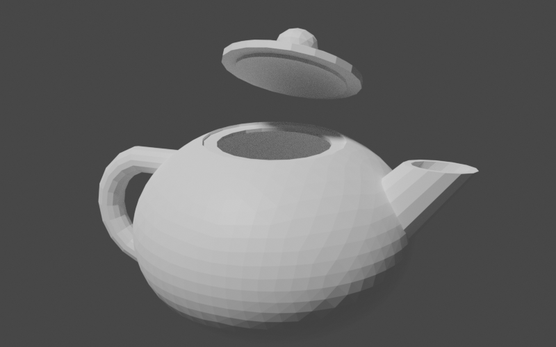
ConclusionIn this tutorial, we've explored creating and combining solid geometries with Commons Geometry. These are powerful features of the library and can be used in a wide range of applications. However, this is just the beginning. Once we have our geometries in place, we can perform other useful tasks, such as computing volume, surface area, and center of mass or performing visibility checks using raycasting or linecasting. Hopefully what you've learned in this tutorial will give you a solid base to build on as you explore these and other features of the library. |